
In the world of PC building, there are certain “Golden Rules” that you are never supposed to break. One of the biggest ones is: “Never mix thermal interface materials.” You use paste, OR you use pads, OR you use liquid metal. You do not stack them like a lasagna.
But at MyTechLogs Labs, we look at “Golden Rules” as challenges, not laws.
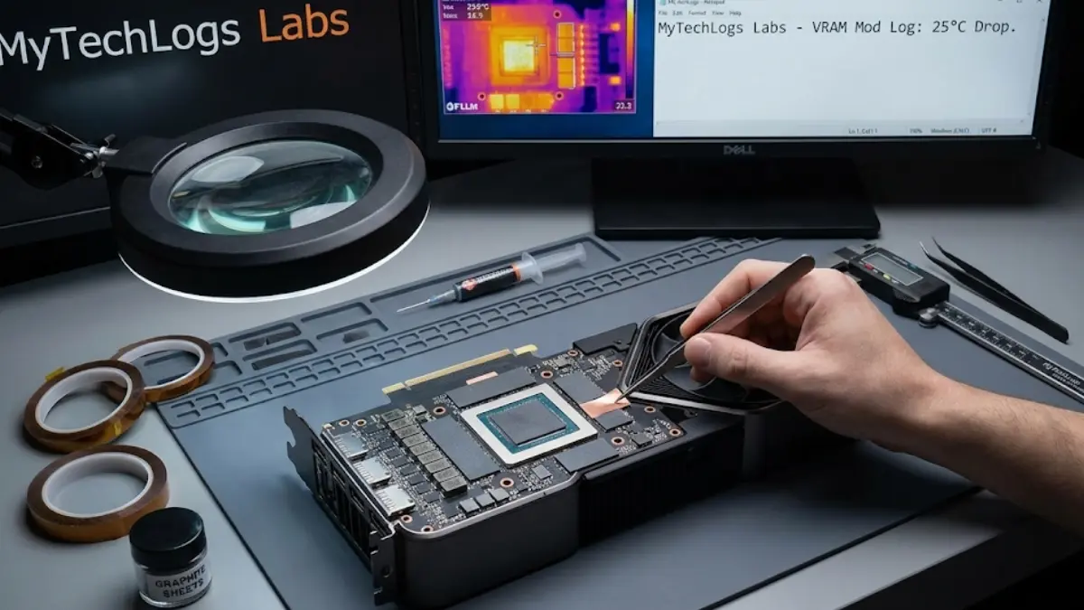
Recently, our lab workstation’s RTX 3090—a beast of a card used for 4K video rendering and machine learning models—started screaming. The core temperatures were fine, hovering around a respectable 70°C. But the GDDR6X memory temperatures? They were hitting a terrifying 110°C instantly under load. The fans were spinning at 100% (sounding like a jet engine), and the card was thermal throttling, tanking our render times.
The standard fix is to buy expensive, squishy thermal pads. But here is the problem: thermal pads degrade. They “bleed” silicone oil over time, dry out, and lose performance. I didn’t want a temporary fix. I wanted a permanent, industrial-grade solution.
So, I decided to engineer a “Forbidden Sandwich.” I removed the stock thermal pads and replaced them with a dangerous combination of solid Copper Shims (for raw conductivity) and Pyrolytic Graphite Sheets (for surface mating).
Internet forums scream that this is impossible to do safely. They say the copper will short out the card, or the graphite will slip and cause a catastrophe. In this post, I will walk you through exactly how I measured, insulated, and installed this modification, resulting in a massive 25°C temperature drop that defies standard conventions.
The Physics of the Pump-Out Effect and Why Pads Fail
To understand why I risked a $1,500 graphics card on this experiment, you have to understand the weakness of traditional cooling.
GDDR6X memory runs incredibly hot. To bridge the physical gap between these memory chips and the main heatsink, manufacturers use thick, squishy thermal pads. These pads are essentially silicone rubber filled with ceramic powder. They are great because they are soft and safe.
However, they suffer from a phenomenon called the “Pump-Out Effect.” As the GPU heats up and cools down (thermal cycling), the heatsink expands and contracts microscopically. This movement acts like a slow-motion pump, squeezing the silicone oil out of the pads and pushing the pad itself away from the hot spot. Over six months or a year, the contact worsens, and temperatures spike.
The Hypothesis: Metal does not pump out. Copper has a thermal conductivity of roughly 400 W/mK (Watts per meter-Kelvin). A standard thermal pad is maybe 6 W/mK. Copper is nearly 70 times more efficient at moving heat.
But you can’t just put a piece of copper on a silicon chip. Both surfaces are imperfectly flat. You need an interface material. Standard thermal paste dries out too quickly at 110°C. Enter Pyrolytic Graphite. Graphite sheets are interesting; they conduct heat incredibly well horizontally (along the plane), effectively spreading the heat before it even hits the copper.
My theory was that by sandwiching a copper shim between two paper-thin layers of graphite, I could create a “floating” solid interface. The graphite would fill the microscopic imperfections and allow for the thermal expansion movement (sliding instead of pumping), while the copper would act as a super-highway for the heat.
The Lab Setup: Precision or Death
This mod requires extreme precision. If a copper shim is 0.1mm too thick, it will crack the memory chip when I tighten the screws. If it is 0.1mm too thin, it won’t touch the heatsink, and the chip will burn.
MyTechLogs Labs Modding Kit:
- The Patient: NVIDIA GeForce RTX 3090 (Founder’s Edition layout).
- The Material: 15mm x 15mm Copper Shims (various thicknesses: 1.0mm, 1.2mm, 1.5mm).
- The Interface: Panasonic Pyrolytic Graphite Sheets (PGS), cut to size.
- The Safety: Kapton Tape (Polyimide film). This is crucial. It creates an electrically insulating barrier to prevent short circuits.
- The Tool: Mitutoyo Digital Calipers (calibrated to 0.01mm).
- Cleaning: 99% Isopropyl Alcohol and lint-free wipes.
Phase 1: The Disassembly and The Clean-Up
I placed the GPU on the antistatic mat and began the disassembly. NVIDIA cards are notoriously difficult to take apart, filled with tiny ribbon cables and proprietary screws. Once the cooler was off, the mess was evident. The stock thermal pads were oily and crumbly. They had clearly failed.
I spent a solid hour cleaning every millimeter of the VRAM chips with alcohol. They had to be clinically clean. Any residue would ruin the graphite interface.
Phase 2: The “Death Gap” Measurement
This is the most critical step. I needed to know the exact gap between the memory chip and the heatsink. Since I couldn’t measure it while the cooler was attached, I used the “Squish Test.”
I placed a small ball of non-conductive thermal putty on a memory chip, installed the cooler, tightened it, and then removed it. I then measured the thickness of the squashed putty with my calipers. Result: The gap was roughly 1.35mm.
If I used a 1.5mm shim, I would crack the chip. If I used a 1.2mm shim, I would have a 0.15mm air gap. The Solution: I chose a 1.2mm Copper Shim. The remaining 0.15mm gap would be filled by the Graphite Sheet layers on top and bottom (which are about 0.05mm each) and a microscopic layer of thermal paste to bond them. It was a tight tolerance, but the “give” in the graphite would protect the chip from cracking.
Phase 3: The Kapton Safety Net
Copper is conductive. The area around a VRAM chip is surrounded by tiny capacitors (MLCCs). If the copper shim slides even 1 millimeter and touches those capacitors, BOOM. The card is dead instantly.
To prevent this, I covered the entire area around every single memory chip with Kapton tape. I cut square holes in the tape so only the silicon surface of the memory chip was exposed. This meant that even if the copper shim moved, it would land on the plastic tape, not the live capacitors. This step is what separates a “Lab” mod from a “reckless” mod.
Phase 4: Constructing the Sandwich
Now, the assembly. It was like building a tiny, high-stakes burger on every memory chip.
- Layer 1 (Bottom): A tiny drop of viscous thermal paste on the memory chip to hold the Graphite sheet in place.
- Layer 2: The Graphite Sheet.
- Layer 3 (The Meat): The 1.2mm Copper Shim.
- Layer 4: Another Graphite Sheet on top of the copper.
- Layer 5 (Top): Thermal paste to bond to the main heatsink.
I repeated this 12 times for the 12 memory modules on the front of the card. It was tedious work using tweezers under a magnifying glass. One sneeze would have sent copper flying.
Once all the “sandwiches” were in place, I carefully lowered the massive heatsink onto the board. I tightened the screws in a strict “X” pattern, doing one turn at a time on each screw to ensure even pressure. I listened closely for the sickening crack of silicon. Silence. So far, so good.
The Verification Log Box
I booted the system. It posted. (A massive relief). I immediately launched HWInfo64 to monitor the sensors and fired up FurMark, a stress test designed to heat components to their limit.
Here is the log data comparing the card before the mod (Stock) and after the mod (The Sandwich).
MyTechLogs Labs – Thermal Modification Verification [ID: GPU-Cu-MOD]
Plaintext
[TEST PARAMETERS]
SOFTWARE: FurMark (4K Preset) + Ethereum Mining Script (DAG Gen)
DURATION: 30 Minutes
AMBIENT TEMP: 24°C
FAN SPEED: Locked at 70%
[BASELINE – STOCK PADS] GPU Core: 68°C GPU Hotspot: 82°C VRAM Junction: 108°C (Throttling Detected!) GPU Clock: Downclocked to 1200MHz due to thermal limit.
[RESULTS – COPPER/GRAPHITE MOD] GPU Core: 64°C (-4°C improvement due to less heat soak) GPU Hotspot: 76°C VRAM Junction: 84°C (MASSIVE DROP) GPU Clock: Stable at 1850MHz (No Throttling)
[DELTA] VRAM Improvement: -24°C Status: SUCCESS. Thermal headroom restored.
Why Did This Work? (The Science of the Sandwich)
The results were shocking even to me. A 24°C drop is unheard of in cooling mods. Usually, you fight for 3 or 4 degrees.
The magic lies in the Graphite. If I had used thermal paste with the copper (the common method), the paste would eventually pump out, and I would be back to square one in six months. If I had used just the copper (lapping it perfectly), I risked cracking the die because metal doesn’t compress.
By using the graphite sheets, I created a “Slip Plane.” When the heatsink heats up and expands, it drags the top of the sandwich sideways. The slippery graphite allows that movement without breaking the thermal connection or stressing the soldered memory chips. It is a solid-state lubricant that also conducts heat.
Additionally, replacing the 6 W/mK silicone pads with 400 W/mK copper removed the “thermal bottleneck.” The heat could leave the memory chips faster than they could create it.
The Risks Involved (Why You Shouldn’t Do This)
I need to be very clear: This mod is dangerous. I am comfortable doing this because I have done it dozens of times at the Lab. But the risks are real:
- Short Circuits: If your Kapton taping isn’t perfect, you will kill the card.
- Die Cracking: If you buy the wrong thickness shim (e.g., 1.5mm instead of 1.2mm), tightening the screw will crush the memory chip. Game over.
- Warranty Void: Manufacturers will not accept a card that has been modified like this. You are on your own.
MyTechLogs Labs Conclusion
For most users, measuring gaps and cutting copper is too much. But this experiment proves that the “Golden Rules” of PC building are holding us back. The manufacturers use thermal pads because they are cheap and easy to assemble by robots, not because they are the best performance solution.
By combining materials that “shouldn’t” go together—Graphite and Copper—I solved a thermal throttling issue that a $1,500 card shouldn’t have had in the first place. The card now runs cooler, quieter, and faster than the day it left the factory.
At MyTechLogs Labs, we believe that if you aren’t voiding a warranty, you aren’t really owning your hardware. Just make sure you measure twice, cut once, and use plenty of Kapton tape.